Why Accurate CAD Drawings Are Critical for Heavy Equipment Manufacturing

Introduction
In heavy equipment manufacturing, precision is not optional; it is foundational. Whether designing jumbo drilling machines for underground mining or large-scale industrial machinery, even the smallest design error can cascade into costly production delays, safety risks, and operational failures. In an industry where components weigh tons, complex, and often custom-engineered, accurate documentation is the backbone of successful manufacturing.
At the same time, the heavy-duty equipment market is witnessing strong global growth, driven by rapid infrastructure development, mining expansion, energy demand, and large-scale industrial projects. The global construction and heavy equipment market is estimated to be valued at over $300–350 billion and is projected to grow at a CAGR of around 6–8% in the coming years. Emerging economies, smart city initiatives, and increased investments in transportation and energy infrastructure are further accelerating this growth.
As demand rises, manufacturers are under increasing pressure to deliver high-performance, reliable machinery faster and more efficiently. This is where CAD drawings play a pivotal role. High-quality, precise CAD designs ensure that every component fits, functions, and performs exactly as intended.
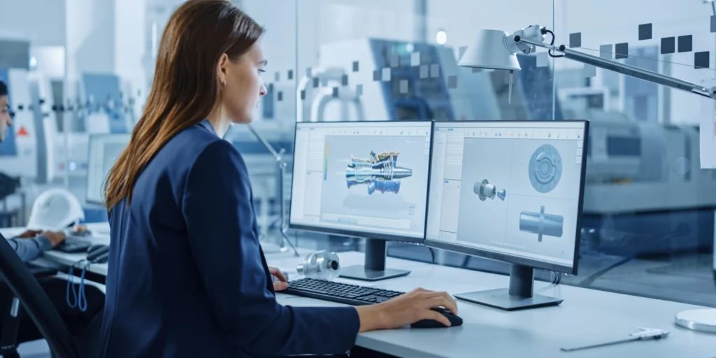
What Are CAD Drawings in Heavy Equipment Manufacturing?
CAD (Computer-Aided Design) drawings are digital representations of machinery components and assemblies used throughout the product lifecycle from concept and design to manufacturing and maintenance.
In heavy equipment manufacturing, CAD drawings typically include:
- 2D CAD drawings: Technical blueprints with dimensions, tolerances, and annotations
- 3D modeling: Detailed digital models that simulate real-world performance
- Assembly drawings: Instructions on how components fit together
- As-built drawings: Final documentation reflecting actual manufactured conditions
These drawings act as a single source of truth, ensuring consistency across engineering, production, and quality teams.
Why Accuracy in CAD Drawings Matters

1. Manufacturing Precision and Quality
Accurate CAD drawings directly impact the precision of manufactured components. Heavy machinery often involves tight tolerances and complex assemblies, where even a minor deviation can lead to misalignment or performance issues.
Precise engineering design ensures:
- Correct fit and function of components
- Structural integrity of large assemblies
- Optimal performance under extreme operating conditions
In industries like mining or construction, where equipment operates in harsh environments, this level of accuracy is critical for durability and safety.
2. Reduced Errors and Rework
Inaccurate CAD drawings are one of the leading causes of production errors. A missing dimension, incorrect tolerance, or outdated revision can result in:
- Scrap materials
- Rework cycles
- Production downtime
By investing in accurate CAD drawings, manufacturers significantly reduce the risk of costly mistakes. This not only improves efficiency but also enhances overall product reliability.
3. Improved Communication Between Teams
Heavy equipment manufacturing involves multiple stakeholders, including:
- Design engineers
- Manufacturing teams
- Quality assurance professionals
- Suppliers and vendors
Accurate CAD drawings serve as a universal language that aligns all teams. Clear and detailed documentation ensures that everyone interprets the design intent correctly, minimizing miscommunication and delays.
4. Compliance with Industry Standards
Industrial machinery design must adhere to strict regulatory and safety standards. Accurate CAD drawings help ensure compliance with:
- Industry-specific guidelines
- Safety regulations
- Quality certifications
Proper documentation also simplifies audits, inspections, and approvals, making it easier for manufacturers to meet global standards.
Role of Advanced CAD Tools
In today’s competitive landscape of heavy equipment manufacturing, advanced CAD tools are not just design software; they are strategic enablers of precision, innovation, and efficiency. As machinery becomes more complex and project timelines more demanding, the role of modern CAD platforms has evolved from simple drafting to comprehensive engineering ecosystems.
Enabling High-Precision Engineering Design
Advanced CAD tools such as AutoCAD, SolidWorks, CATIA, and Revit / BIM allow engineers to create highly accurate 2D CAD drawings and 3D models with exact dimensions, tolerances, and material specifications.
These tools eliminate many of the manual errors associated with traditional drafting by:
- Automating dimensioning and constraints
- Maintaining design intent through parametric relationships
- Ensuring consistency across multiple components and assemblies
For heavy equipment, where components must fit perfectly within large assemblies, this level of precision is critical to achieving manufacturing accuracy.
Parametric and Feature-Based Modeling
One of the most powerful capabilities of modern CAD tools is parametric modeling. This allows engineers to define relationships between different parts of a design so that any modification automatically updates related features.
For example:
- Changing the diameter of a shaft automatically adjusts mating components
- Updating load requirements can dynamically modify structural elements
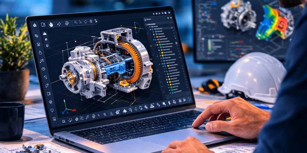
Simulation and Performance Validation
Advanced CAD platforms go beyond design by integrating simulation capabilities such as:
- Stress and strain analysis
- Thermal performance testing
- Motion and kinematics simulation
- Fluid dynamics (in some systems)
These simulations allow engineers to validate designs before physical production, helping to:
- Identify potential failures early
- Optimize material usage
- Improve safety and durability
In heavy equipment manufacturing, where prototypes are expensive and time-consuming, simulation-driven design can save both time and cost while improving product reliability.
Improved Visualization and Design Clarity
With 3D modeling, stakeholders can visualize complex assemblies realistically and interactively. This improves:
- Design reviews and approvals
- Cross-functional collaboration
- Client communication
Engineers, manufacturers, and even non-technical stakeholders can better understand how a machine will look and function. This reduces ambiguity and ensures alignment before production begins.
How Expert CAD Support Makes a Difference
At ProtoTech Solutions, we bring a strong combination of engineering expertise, advanced CAD capabilities, and industry-focused experience to support complex heavy equipment manufacturing requirements.
With deep expertise across industry-leading platforms such as AutoCAD, SolidWorks, CATIA, and Revit / BIM, experienced engineering teams can deliver highly accurate, production-ready CAD drawings tailored to complex heavy equipment requirements. From precise 2D CAD documentation to advanced 3D modeling and design optimization, the focus remains on improving manufacturing accuracy, reducing rework, and accelerating project timelines.
By focusing on accuracy and design standardization, ProtoTech helps manufacturers minimize errors, reduce costly rework, and streamline communication between design, engineering, and production teams.
Whether it’s supporting R&D initiatives, modernizing legacy designs, or handling large-scale CAD conversion projects, ProtoTech Solutions acts as a reliable engineering partner, helping heavy equipment manufacturers improve efficiency, reduce costs, and stay competitive in a rapidly evolving global market. Contact us today for outsourcing mechanical engineering drawing services.