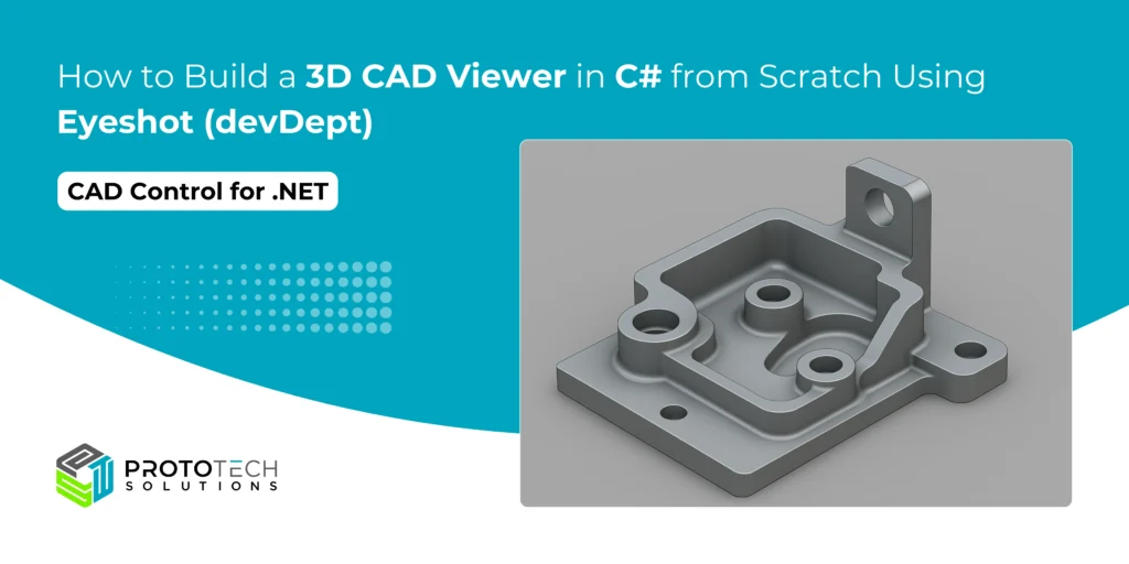
How to Build a 3D CAD Viewer in C# from Scratch Using Eyeshot (devDept)

Eyeshot is a CAD control designed for .NET developers. It seamlessly integrates with Windows Forms (WinForms) and Windows Presentation Foundation (WPF), offering robust tools for building engineering-focused desktop applications. Eyeshot comes with four specialized Visual Studio toolbox components:
- Design – Enables 2D and 3D geometry creation and editing
- Drawing – Automatically generates 2D views from 3D models
- Simulation – Supports geometry validation through linear static analysis
- Manufacture – Provides CNC toolpath creation and simulation
Ideal for developers in CAD, CAM, CAE, and other technical domains, Eyeshot brings professional-grade modeling and visualization features directly into the .NET environment.
Eyeshot supports standard formats like STL, OBJ, IGES, STEP, DWG, and more. It’s powerful yet relatively simple to set up, which makes it ideal for building a custom 3D CAD viewer.
Creating a 3D CAD viewer in C# might sound daunting, but with the right tools, it’s surprisingly straightforward. Eyeshot is a powerful .NET CAD control that handles heavy lifting like rendering, file parsing, and user interactions, letting you focus on customization. In this guide, you’ll build a functional CAD viewer from scratch, complete with model loading, navigation, and basic editing. Let’s dive in!
Requirements
Before we start coding, make sure you have:
- Visual Studio 2025 (Community or higher)
- Eyeshot NuGet package (install via Install-Package devDept.Eyeshot)
- A valid Eyeshot license (trial available)
- Basic C# and WPF knowledge
Step 1: Project Setup
Create a new WPF App in Visual Studio:
- Open Visual Studio → “Create a new project” → “WPF Application.”
- Name your project (e.g., CadViewerApp).
- Install Eyeshot:
Install-Package devDept.Eyeshot 4. Add the Eyeshot namespace to MainWindow.xaml:
xmlns:eyeshot="clr-namespace:devDept.Eyeshot;assembly=devDept.Eyeshot" Step 2: Designing the Viewer Interface
In MainWindow.xaml, add the Eyeshot Model control:
<Grid>
    <eyeshot:Model x:Name="model1" />
</Grid>
This creates a blank 3D viewport. In MainWindow.xaml.cs, initialize Eyeshot:
public MainWindow()
{
    InitializeComponent();
    model1.Renderer = devDept.Eyeshot.RendererType.OpenGL; // Use hardware acceleration
    model1.StartWork(InitModel);
}

private void InitModel()
{
    model1.SetView(viewType.Trimetric); // Default 3D view
    model1.ZoomFit();
}
This sets up OpenGL rendering and a trimetric camera view
Step 3: Loading CAD Models
Eyeshot supports DWG, STL, STEP, and more. Add a button to load files:
private void LoadModel(string filePath)
{
    model1.Entities.Clear();
    devDept.Eyeshot.Translators.ReadFile readFile = new devDept.Eyeshot.Translators.ReadFile(filePath);
    readFile.DoWork();
    model1.Entities.AddRange(readFile.Entities);
    model1.ZoomFit();
}
Call this method with a file dialog (e.g., on a button click). For example:
var dialog = new OpenFileDialog();
if (dialog.ShowDialog() == true)
{
    LoadModel(dialog.FileName);
}
Now your app can display complex models like bolts, buildings, or machinery
Step 4: Adding Navigation Tools
Enable intuitive camera control:
// In InitModel():
model1.ActionMode = actionType.Navigate; // Pan/zoom/rotate
model1.ToolBar.Visible = true; // Show default toolbar
Customize interactions:
- Zoom/pan: Use mouse wheel + right-click.
- Rotation: Hold the left mouse button.
For touch screens, enable multi-touch:
model1.TouchEnabled = true;Step 5: Basic Editing Features
Extend functionality with simple editing. For example, add a button to create a cube:
private void AddCube()
{
    var cube = Mesh.CreateBox(10, 10, 10); // 10x10x10 cube
    cube.Color = System.Drawing.Color.Blue;
    model1.Entities.Add(cube);
    model1.Invalidate(); // Refresh view
}
Or implement real-time updates:
// Move an entity along the X-axis
var entity = model1.Entities[0] as Mesh;
entity.Translate(5, 0, 0);
model1.Invalidate();
Step 6: Advanced Customization (Optional)
For parametric design, link UI controls to Eyeshot. Example: dynamic extrusion via slider:
// XAML: Add a Slider named "extrudeSlider"
private void extrudeSlider_ValueChanged(object sender, RoutedEventArgs e)
{
    if (model1.Entities.Count > 0 && model1.Entities[0] is Region)
    {
        var region = (Region)model1.Entities[0];
        var extruded = region.ExtrudeAsMesh(extrudeSlider.Value);
        model1.Entities[0] = extruded;
        model1.Invalidate();
    }
}
Step 7: Save and Export
Need to export or save modified models?
devDept.Eyeshot.Translators.WriteSTL writer = new devDept.Eyeshot.Translators.WriteSTL(viewport.Entities, "output.stl", true);
writer.DoWork();
Ready to Build Your Own 3D CAD Viewer?
You’ve just built a basic but powerful 3D CAD viewer in C# using Eyeshot. With just a few lines of code, you now have the foundation to view and interact with CAD models in your custom application.
Download the Eyeshot SDK, fire up Visual Studio, and build your first 3D viewer today. If you found this tutorial helpful, share it with a fellow developer.
Got a question? Let our experts provide you with an answer. At ProtoTech Solutions, we have developed many 3D CAD applications for our global clients using the Eyeshot tool.


