Building a Custom 3D CAD Viewer Using OpenSceneGraph: Complete Developer Guide
When standard 3D engines like WebGL frameworks or game engines (like Unreal or Unity) hit a performance wall with massive, multi-gigabyte industrial CAD assemblies, desktop-native scene graphs remain the gold standard.
OpenSceneGraph (OSG) is an open-source, high-performance 3D graphics toolkit used extensively in engineering, simulation, and aerospace. Because it sits directly on top of low-level OpenGL, it gives developers granular control over memory management, state sorting, and culling operations—exactly what you need to render millions of polygons smoothly.
Whether your goal is CAD model review, digital twin visualization, BIM coordination, product configuration, manufacturing planning, or engineering collaboration, OpenSceneGraph offers a proven and scalable platform for developing high-performance 3D CAD viewers tailored to your specific business requirements.
At ProtoTech Solutions, we have designed and developed many custom 3D CAD viewers for global clients based on their business, engineering, and visualization requirements. In this guide, we explain how to build a custom, production-grade 3D CAD viewer using OpenSceneGraph and C++.
Why OpenSceneGraph for CAD Viewers?
CAD data presents unique rendering challenges that game engines are not optimized to handle:
- B-Rep and Parametric Tessellation: CAD files are stored as mathematical boundaries (B-Rep) rather than raw triangles. When converted to meshes, they result in dense polygon counts and highly variable topology.
- Deep Hierarchical Structures: Industrial models contain thousands of sub-assemblies and nested parts, which can choke standard rendering pipelines with draw calls.
- Precision Requirements: Traditional engines use 32-bit single-precision floats, which cause geometric jittering or “z-fighting” artifacts when viewing tiny components on a massive machine assembly.
OSG natively solves these issues through a highly optimized Directed Acyclic Graph (DAG) architecture, automatic view-frustum culling, occlusion culling, and state-sorting mechanisms that minimize CPU-to-GPU state changes.
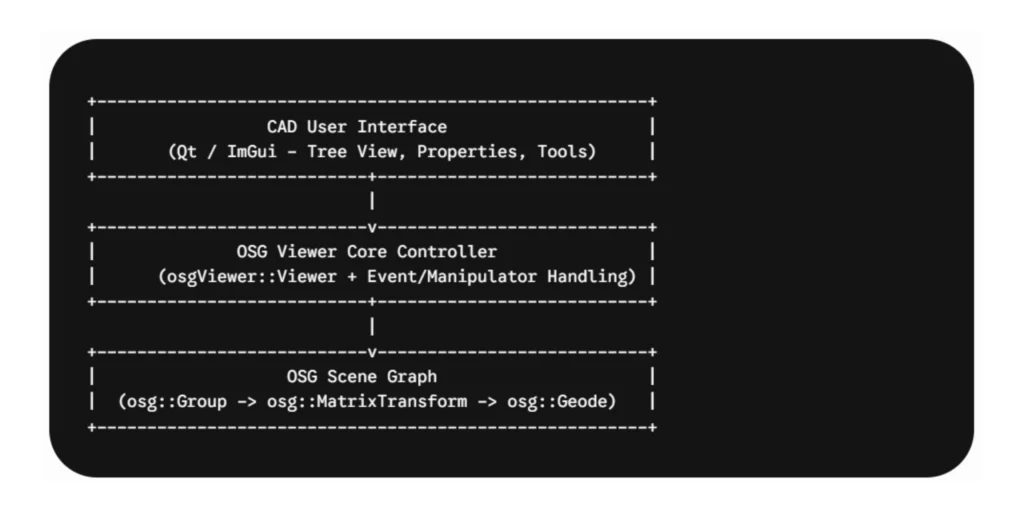
Core Architecture of an OSG Viewer
To build a usable CAD viewer, your application architecture must bridge the gap between raw data storage and interactive rendering. The setup requires three core layers:
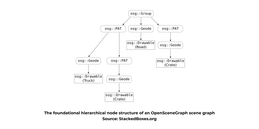
Understanding the Node Types
As shown in the structural diagram above, OSG manages data across distinct node types:
- osg::Group: A general structural node that can hold multiple child nodes.
- osg::MatrixTransform / osg::PAT (PositionAttitudeTransform): Handles translation, rotation, and scaling of sub-assemblies.
- osg::Geode (Geometry Node): The leaf node of the graph. In modern OSG versions, geometry is attached directly to groups, but understanding the Geode pattern is critical for handling legacy CAD plugins.
- osg::Geometry (inside Drawables): Holds the actual vertex arrays, normals, texture coordinates, and primitive sets (triangles, lines).
Step-by-Step Implementation
Let’s implement a minimal, high-performance CAD viewer capable of loading a file, setting up engineering-focused lighting, and handling CAD-style mouse interactions.
Step 1: Initialize the Viewer and Window Context
First, we instantiate our primary window context and view controller.
#include <osgViewer/Viewer>
#include <osgDB/ReadFile>
#include <osgGA/TrackballManipulator>
#include <osgViewer/ViewerEventHandlers>

int main(int argc, char** argv) {
    // Initialize the viewer
    osgViewer::Viewer viewer;

    // Set up a standard desktop windowing context
    viewer.setUpViewInWindow(100, 100, 1280, 720);

    // Create a root node for our scene graph
    osg::ref_ptr<osg::Group> root = new osg::Group();
Step 2: Implement a CAD Camera Manipulator
Engineers expect a specific camera style: middle mouse button to pan, scroll wheel to zoom to cursor point, and left mouse button to orbit.
While osgGA::TrackballManipulator is the default, a custom manipulator overriding mouse events is often necessary for true CAD behavior. For this baseline guide, we will leverage the robust default camera controls and attach the statistics handler.
// Configure standard camera manipulation
    viewer.setCameraManipulator(new osgGA::TrackballManipulator());

    // Add useful utility event handlers (Press 's' to see frame rate / stats)
    viewer.addEventHandler(new osgViewer::StatsHandler());
Step 3: Load Data and Optimize the Scene Graph
When loading models (e.g., via standard formats like .step or .iges processed through an intermediary tessellator like Open CASCADE, or native formats via OSG plugins like .obj, .fbx), the scene graph can often be messy or redundant. We use OSG’s built-in optimizer to clean it up before rendering.
// Load the 3D CAD model geometry
    // Note: Production viewers will parse STEP/IGES via Open CASCADE and populate osg::Geometry
    osg::ref_ptr<osg::Node> cadModel = osgDB::readNodeFile("sample_assembly.obj");

    if (!cadModel) {
        osg::notify(osg::WARN) << "Failed to load CAD model geometry." << std::endl;
        return 1;
    }

    // Optimize the incoming scene graph structure
    osgUtil::Optimizer optimizer;
    optimizer.optimize(cadModel.get(), osgUtil::Optimizer::ALL_OPTIMIZATIONS);

    // Attach optimized model to the scene root
    root->addChild(cadModel.get());
Step 4: Configure Engineering Shader States and Rendering Pipeline
CAD visualization requires clean, distinct lighting to reveal surface defects and geometric contours. We disable default global lighting variations and apply explicit material shading rules.
// Get the state set of the root node to apply global rendering properties
    osg::ref_ptr<osg::StateSet> stateSet = root->getOrCreateStateSet();

    // Enable depth testing explicitly to prevent z-buffer artifacts
    stateSet->setMode(GL_DEPTH_TEST, osg::StateAttribute::ON);

    // Enable standard OpenGL lighting calculations
    stateSet->setMode(GL_LIGHTING, osg::StateAttribute::ON);
    stateSet->setMode(GL_LIGHT0, osg::StateAttribute::ON);

    // Ensure double-sided lighting is enabled so internal cavities are visible
    osg::ref_ptr<osg::LightModel> lm = new osg::LightModel();
    lm->setTwoSided(true);
    stateSet->setAttributeAndModes(lm.get(), osg::StateAttribute::ON);
Step 5: Execute the Performance-Optimized Render Loop
OSG abstracts away the underlying graphics API pump loop, updating animations, tracking dirty state sets, and efficiently handling frame dispatches.
// Bind our populated scene graph to the view frame
    viewer.setSceneData(root.get());

    // Real-time render loop execution
    return viewer.run();
}
Advanced CAD Optimizations for High-Polygon Performance
Once your baseline application renders shapes cleanly, you must optimize for industry-sized datasets. Implementing the following techniques will prevent your frame rates from plummeting:
1. Vertex Buffer Objects (VBOs) and Display Lists
Ensure all geometry arrays are explicitly bound to the graphics card VBO memory rather than being parsed via slow CPU-client rendering states every frame:
geometry->setUseVertexBufferObjects(true);
geometry->setUseDisplayList(false); // Deprecated in modern OpenGL workflows
2. Instanced Rendering for Repetitive Fasteners
Industrial assemblies often contain thousands of identical components (screws, bolts, washers). Instead of duplicating nodes, use an osg::Group node structure that points to a single instanced osg::Geometry primitive set, modifying position matrix parameters dynamically via hardware arrays.
3. Vertex Normal Sharing
CAD geometry requires sharp edges alongside smoothly curved fillets. Ensure your tessellation pipeline uses index arrays wisely—sharing normals across continuous patches but duplicating vertices along sharp break lines to preserve visual fidelity without inflating your memory overhead.
Elevate Your 3D Workflow
Building a custom 3D CAD viewer from scratch gives you unparalleled control over your data pipelines, rendering performance, and engineering workflows. By leveraging OpenSceneGraph’s powerful node hierarchy, aggressive culling options, and hardware optimization strategies, you can turn massive industrial assemblies into fluid, interactive experiences.
However, taking a proof-of-concept desktop viewer to a production-grade enterprise application—complete with complex file format translators (like STEP, IGES, and JT), precise measurement toolsets, cross-platform compilation, and modern UI integration—requires deep, specialized expertise.
Partner with the CAD Development Experts
You don’t have to build it alone. If you want to accelerate your time-to-market or need a high-performance custom 3D CAD viewer tailored to your exact business specifications, partner with ProtoTech Solutions.
We have designed, engineered, and deployed robust 3D CAD visualization applications for clients worldwide across desktop, mobile, and cloud environments. Our dedicated team of graphics experts can handle the heavy lifting of geometric engine optimization, CAD format interoperability, and seamless user experience design.
Ready to transform your 3D data? Connect with ProtoTech Solutions today to discuss your project requirements and see how we can bring your custom 3D viewer vision to life.
Frequently Asked Questions (FAQ)
What is OpenSceneGraph used for?
OpenSceneGraph is an open-source 3D graphics framework used for CAD visualization, simulation, digital twins, GIS applications, engineering software, and scientific visualization.
Can OpenSceneGraph handle large CAD assemblies?
Yes. OpenSceneGraph supports large-scale models through level-of-detail management, culling techniques, geometry instancing, and multi-threaded rendering.
Which CAD formats can be viewed using OpenSceneGraph?
OpenSceneGraph can visualize geometry converted from formats such as STEP, IGES, STL, OBJ, FBX, JT, Parasolid, and many proprietary CAD formats.
Is OpenSceneGraph suitable for commercial CAD software?
Yes. Many commercial engineering and simulation applications use OpenSceneGraph because of its flexibility, scalability, and open-source architecture.
Can OpenSceneGraph be integrated with Qt?
Yes. Qt is one of the most popular frameworks used with OpenSceneGraph to build professional CAD, engineering, and visualization applications.
What are the advantages of building a custom CAD viewer?
A custom CAD viewer provides complete control over performance, workflows, user experience, integration capabilities, security requirements, and engineering-specific functionality.